Rod Bantjes, “FB-BO-26-01_Flip-Chain Polyorama.html,” created 22 July, 2026; last modified, 22 July, 2026 (https://people.stfx.ca/rbantjes/).
Flip-Chain Polyorama
François Binétruy Collection,[1]
France, ca.1858
Dimensions: H=47.8 cm, W=28.6 cm, D=46.3
Lens: ⌀=8.8 cm, ƒ=23 cm
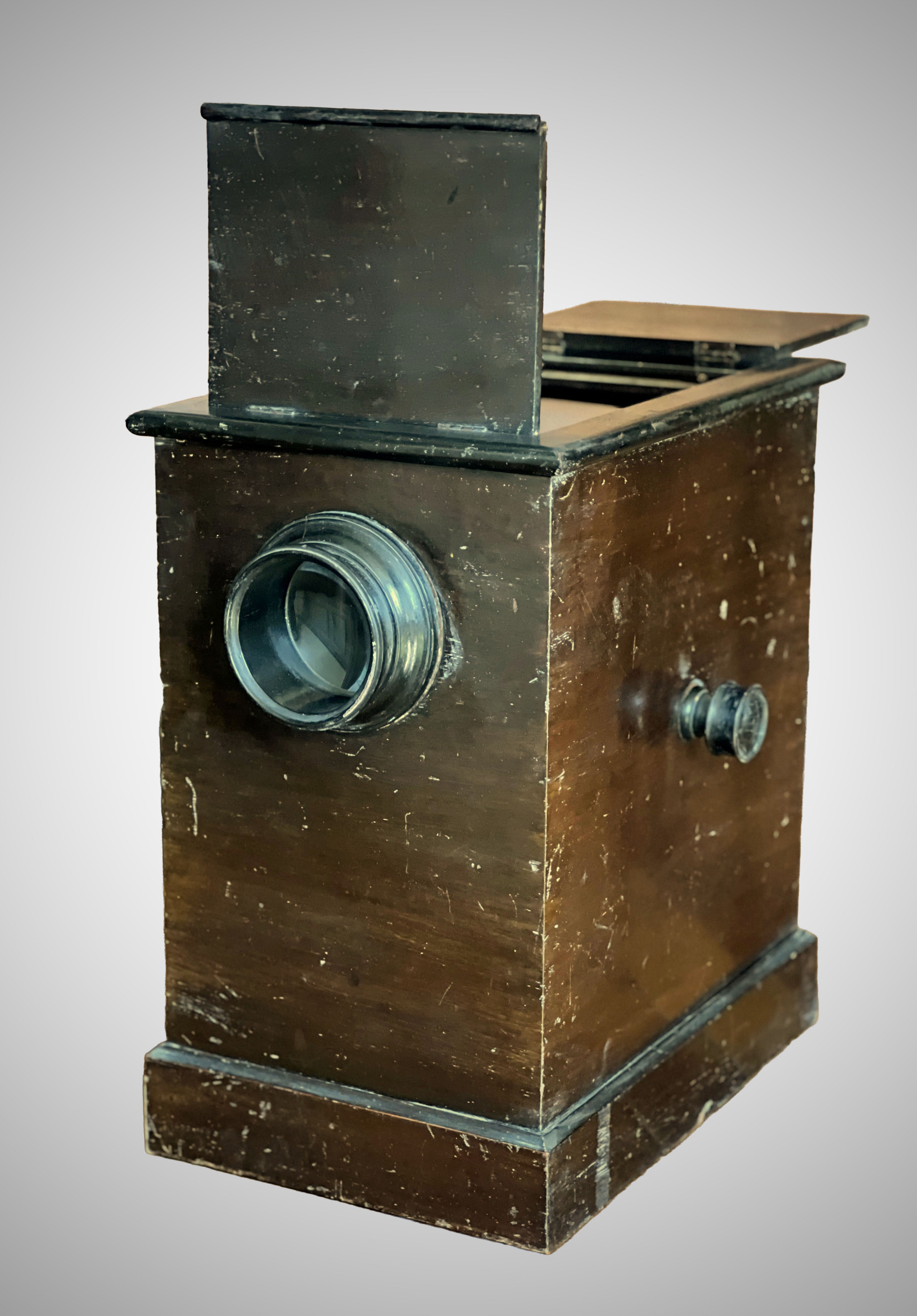 |
Figure FB-BO-26-01.1 – Flip-Chain Polyorama |
| Photo © Rod Bantjes. |
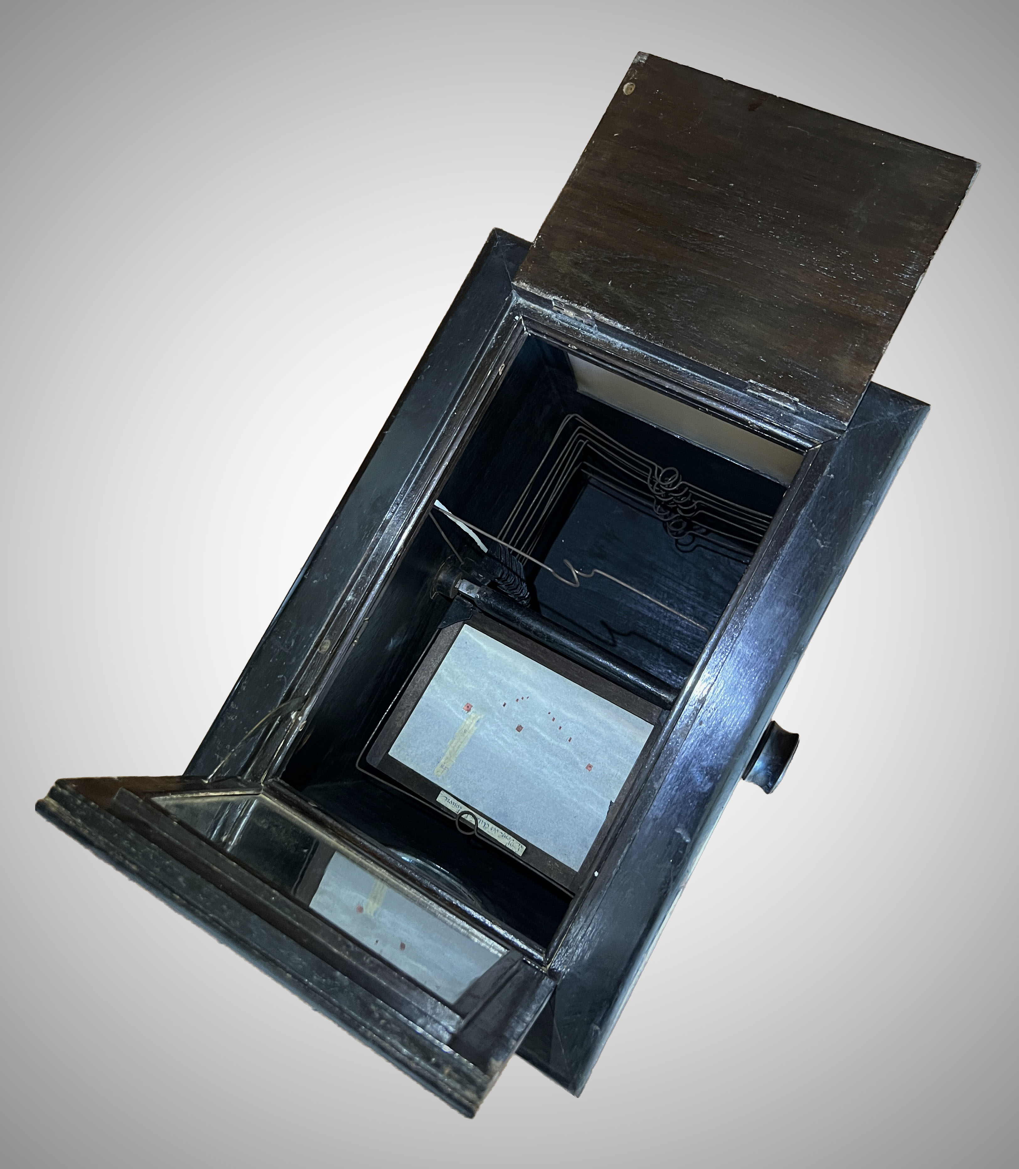 |
Figure FB-BO-26-01.2 – Flip-Chain Mechanism |
| Photo © Rod Bantjes. |
This is the only known example of an “optical machine ” that uses a flip-chain mechanism to change from one image to the next. It is included in the Optical Machine Taxonomy as a member of the Boîte dioramique family. That family is defined by the type of image used – a translucent paper diorama that can be front or back-illuminated for different visual effects.
Flip-Chain Mechanism – Beckers Stereoscope: The flip-chain mechanism is better known from “table-top” stereoscopes that contain multiple images on a continuous loop. Alexander Beckers' patent diagram (Figure FB-BO-26-01.3) shows the inner workings. Here there are 13 casements (Beckers' fig. 3) that each hold one stereogram. They are connected by hinges in a continuous chain. The chain wraps around two spindles with square cross-sections. They wrap tightly because the sides of the squared spindle are the same width of the base of each casement. The squared shape means that when the top casement is vertical in the viewing area, the casements preceding and following it lie flat and out of sight. The drive-spindle is activated by two wooden knobs outside the box on either side.
Flip-Chain Mechanism – Polyorama: There are different styles of flip-chains, but the one in this polyorama is almost identical to the Beckers patent. It has the same squared axles that function in the same way. They are similarly driven by turned wooden knobs. I did not count the casements because the chain was broken and I did not want to put strain on it by revolving it. However, I estimate that there were 19 or 20. This is a relatively small number compared to most flip-chain stereoscopes. With relatively short chains, this and the Beckers 1857 box have the same squat shape. The casements are of a slightly different design from the Beckers example – a heavy steel wire with a wide loop bent into the top to grip the top of the plaque -frame (see Figure FB-BO-26-01.2).
Images: The plaques dioramique measure 15 x 20 cm, the second-smallest of the 5 standard sizes. About half of the images are still in their frames. It would be interesting to learn the subjects of each and the order in which they are stacked in case there is some form of narrative or thematic relationship between them.
Illumination: The front-flap is designed to reflect light by means of a mirror to illuminate the front of the views. The mirror is more common in Brewster stereoscopes. Henri Lefort, maker of most Boîtes dioramique typically uses a gold foil for this purpose. Back-illumination is achieved with a ground glass but without a flap that would allow the user to vary the amount of light. Again, that is typical of Brewster stereoscopes whereas Lefort invariably uses a back-flap.
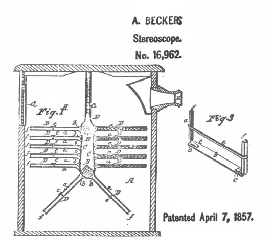 |
Figure FB-BO-26-01.3 – Beckers Patent 1857 |
| Source: William Bray, 1979, “The Langenheims of Philadelphia,” Stereo World 6(9): 13. |
Nexes of Cross-Inspiration: From 1849 onward there was cross-inspiration between the Brewster stereoscope, invented that year, and Boîtes dioramique, the most popular of which, the Polyorama Panoptique, was patented in the same year. Whoever made the Flip-Chain Polyorama surely had seen the Beckers device and Becker had no doubt seen optical boxes. His viewers were probably the first application to the stereoscope of the idea of a cabinet-style viewer that sits on a table-top. However, that style had been common in optical machines since the 18th century (see for example the Pillar Box)
Flip-Chain Mechanism – Precedents and Antecedents: Photographer Antoine Claudet had earlier patented flip-devices for changing stereoscopic images: one in 1853 and one in 1855. The 1853 device consists of four casements on a spindle, similar in principle to the Peep Egg. Claudet's devices are clock-work driven. The 1855 patent is also for a semi-automated spindle-mechanism with a shutter. Here he also mentions the possibility of a continuous belt holding a much larger number of images.[2]. The belt or chain requires two axes; the spindle only one. The flip-book style of the Kinora can be thought of as a hybrid between the spindle and the flip-chain. It pivots around a single axle like a spindle-mechanism but supports myriad views like the chain or belt systems. The kinora flip-mechanism has a simple form of automated stop-action, like Claudet's 1855 device, which allows the transition from images presented in series to an animated image from a series of component images. Click here to learn more about the origins of the idea of stop-motion animation in the 1830s.
Endnotes:
[1] We are grateful to M. Binétruy for allowing us access to his superb private collection of optical devices.
[2] Wing, Paul. Stereoscopes: The First One Hundred Years. Nashua, N.H.: Transition, 1996, 220-1.